ELECTRICAL ENGINEERING SERVICES
Control Panel Accessories
Ammeter Selector Switch
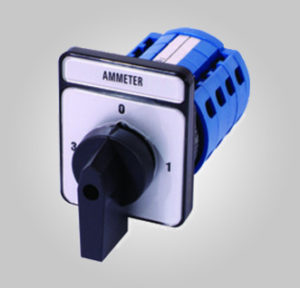 The Ammeter Selector Switch – as the name suggests – is connected to an Ammeter, the purpose being monitoring of current in all the three phases (and, if needed, also in the neutral) using only one ammeter. The Selector switch provided for ammeter is to check the amount of current taken from each phase supply ; ie,R,Y,B. Each phase supply should be covered with a Current Transformer (CT) with the rated Amps capacities. The two lead of each phase CT are connected to the respective leads in the selector switch of the ammeter.
Comb Busbar
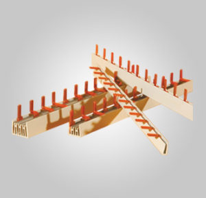 Al Inshrah’s product range comprises fork and prong connecting busbars for making connections of low voltage modular equipment. The insulated busbars provide permanent and safe connections among various items of low voltage modular equipment in switching stations. We make high quality connecting busbars. Al Inshra busbars are made of PVC material, M1E copper, has an insulating strength of 2.5KV and ensures stable operation from -20 degree Celsius to +50degree Celsius.
Control Transformers
![]() A control transformer is a device used to transform or “step down” a high main circuit voltage to a lower voltage which is then used to operate the control or switching components of the main circuit. These devices are commonly used in industrial starter circuits where the main circuit voltage is not suitable for use in the control circuit and where a separate control circuit feed would not be practical. For example in a starter panel designed to start a 500 volt electric motor, the contactors and relays used to switch the motor on or off would typically use electromagnetic coils rated for a far lower voltage. To supply this voltage without the need for a separate power feed, power is tapped off the main incoming 500 volt feed and passed through a control transformer which would then supply the lower control circuit voltage.
A control transformer is a device used to transform or “step down” a high main circuit voltage to a lower voltage which is then used to operate the control or switching components of the main circuit. These devices are commonly used in industrial starter circuits where the main circuit voltage is not suitable for use in the control circuit and where a separate control circuit feed would not be practical. For example in a starter panel designed to start a 500 volt electric motor, the contactors and relays used to switch the motor on or off would typically use electromagnetic coils rated for a far lower voltage. To supply this voltage without the need for a separate power feed, power is tapped off the main incoming 500 volt feed and passed through a control transformer which would then supply the lower control circuit voltage.
Heavy electrical machinery that starts automatically or remotely generally makes use of contactors which rely on an electromagnetic force to close them to start the machinery. This force is created by an electric coil placed in the center of a laminated steel core. These coils are typically designed to operate at fairly low voltages, ranging from 110 volts to as low as 12 volts. As these machines themselves typically run on far higher voltages, this creates the need for a separate control voltage feed. Instead of having to run separate cables or install extra sets of bus bars, it is far simpler to use the main circuit voltage and step it down with a control transformer to the appropriate control voltage.
Low control circuit voltages are used for various reasons including the fact that parts of the control circuit include push buttons in a remote control room, on the starter panel door, and at the machine itself. It would not be wise to have high voltages used in these applications for obvious safety reasons. It is also undesirable to have densely packed control wiring carrying very high voltages inside the starter panel either. For these reasons, lower voltages are typically used in control circuits.
Another benefit of using a control transformer is the inherent stability of the voltage supplied from a transformer as well as its ability to handle extreme peaks in demand. When the start button on a motor starter is pushed and the contactor coil energizes, there is a very brief (typically 30 to 50 milliseconds) surge in current demand known as an “inrush current”. This peak can exceed 10 times the normal current flow, and transformers handle these peaks far more efficiently than a conventional supply.
Using a control transformer to supply control power thus allows a lower, safer and more efficient control circuit voltage to be used in high working voltage applications. The excellent inrush current handling characteristics of transformer supplied power also makes for a more efficient power supply. Lastly, the use of lower voltages in a control circuit make for far safer use by workers using stop and start buttons in hazardous environments.
LED
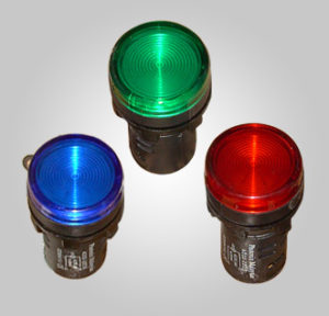 LED is one of the control panel accessories that Al Inshrah offers. Light emitting Diode also called LED is a two lead semiconductor light source that resembles a basic pn-junction diode and it emits light. Al Inshrah is committed to providing its customers with outstanding services and the highest quality products in LED lighting. We work to continuously develop new product lines for a variety of applications including homes, landscape, automotive, boating and recreation. We make you save energy and money with the new technology LED bulbs and providing the same light output.
Limit Switch
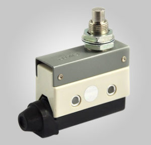 A limit switch is used to limit the activation of an electrical circuit. When a circuit is “closed,” it allows the flow of electrical current through the switch to pass to the device being powered. When the switch is “open,” the switch is disengaged and no electrical power will pass through it. Whether the limit switch is open or closed is generally determined either by the position of a device being powered or by a set amount of time a device requires to complete a specific task.
The most common type of limit switch is a mechanical limit switch. This switch tracks the location of a specific item and opens or closes when that item reaches a specific location. The switch is activated by physical contact, or lack thereof. For example, a light inside a car often turns on when one of the doors is opened.
Another type of limit switch is a centrifugal switch. This switch gauges and is activated strictly by the speed of the item being monitored. While a centrifugal switch can have many purposes, it is widely used as a safety mechanism to shut down a device if it reaches a speed higher or lower than its accepted safety rating. These switches are commonly used in engines and motors.
Limit switches are most commonly used in industrial settings. They are used for everything from controlling a hoist motor to providing pressure control to ensuring worker safety. Switches can be used to start, stop or reverse assembly lines; as sensors to detect a completed activity, such as stopping a robotic arm from stacking materials past a certain height; or as detectors to engage such safety equipment as fire doors in the event of an emergency. Usage examples are endless.
Household environments make use of limit switches as well. A standard garage door opener is a good example. The opener has two limit switches: one to control how long electrical power is supplied to the motor powering the opener, and one to control the travel time of the door as it moves up or down. When the door reaches a certain point the switches open, thus stopping the door from hitting the motor at the top or crashing into the ground at the bottom.
Micro Switch
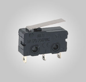 A micro-switch works by detecting the movement of physical objects and indicating it to an electrical circuit. It is normally used to identify objects on conveyor belts, in security alarms, to tell elevators where to stop and to let microwaves know when the door is closed. The micro switch works by using very physical force through the use of a tipping-point mechanism. The switching happens reliably at specific and repeatable positions of the actuator, which is not necessarily true of other mechanisms. Internally, it has a flat metal spring that must be bent to activate the switch. Inside is a small curved spring.
Panel Fan
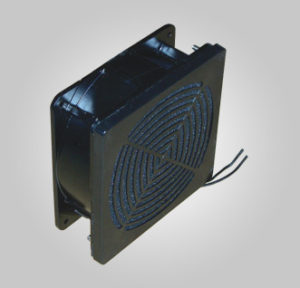 Panel cooling fan is used to move heated air away from the components and draw cooler air over them.
Panel Heater
 Panel heaters work by heating a large infrared surface made of stainless steel, ceramic, quartz cloth or high temperature glass, with quartz cloth heaters being the most common type. Because the heating occurs over a larger area than with other types of space heaters, there is less chance of uneven heating. Their constant temperature ensures the outside of the unit does not reach the extreme temperatures experienced with other types of space heaters, thus reducing the chance of being burned with this type of heater over other types.
Push Button
 A push-button is a simple switch mechanism for controlling some aspect of a machine or a process. Buttons are typically made out of hard material, usually plastic or metal.The surface is usually flat or shaped to accommodate the human finger or hand, so as to be easily depressed or pushed. Buttons are most often biased switches, though even many un-biased buttons (due to their physical nature) require a spring to return to their un-pushed state.
Siren
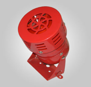 Siren is a piece of equipment which produces loud and high pitched warning sound. We offer you the best siren effects at unbeatable prices. Such standard audible warning sounds are not required by many of our clients and in great demand. The most modern sirens nowadays are civil defense or air raid sirens, sirens on emergency service vehicles such as ambulances, police cars , and fire engines. Most fire sirens have a single alarm sound and are mechanically driven by electric motors with a rotor attached to the shaft. There are even electronically driven speakers, though not very common. Electronic sirens incorporate circuits such as oscillators, amplifiers and modulators to synthesize a selected tone.
Step Switches
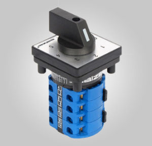 In electrical controls, a stepping switch or uniselector (UK), also known as a stepping relay, is an electromechanical device which allows an input connection to be connected to one of a number of possible output connections, under the control of a series of electrical pulses. It can step on one axis (called a uniselector), or on two axes (a Strowger switch). The major use for these devices was in early automatic telephone exchanges (commonly called Strowger or step-by-step exchanges or steppers) to route telephone calls. Later, they were often used in such equipment as industrial control systems.
Thermostat
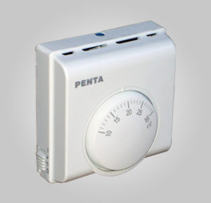
A thermostat is a component of a control system which senses the temperature of a system so that the system’s temperature is maintained near a desired setpoint. The thermostat does this by switching heating or cooling devices on or off, or regulating the flow of a heat transfer fluid as needed, to maintain the correct temperature.
Time Dock
 A thermostat is a component of a control system which senses the temperature of a system so that the system’s temperature is maintained near a desired setpoint. The thermostat does this by switching heating or cooling devices on or off, or regulating the flow of a heat transfer fluid as needed, to maintain the correct temperature.
Timer On Delay Off Delay
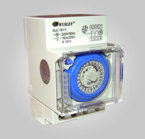
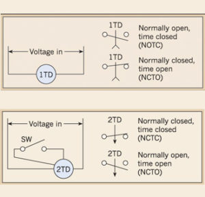 TDRs are available as plug-in devices, much like plug-in control relays. However, they are also available in a range of other forms, including base-mounted devices and direct IEC DIN-mounted controls. For instance, a TDR can be fixed on a motor starter. In this application, energizing the motor starter causes the timing function to begin; contacts within the device operate when timing is complete. Electronic, starter-mounted TDRs are also available. Some TDRs have solid-state outputs instead of relay outputs.
Traditionally, TDRs were available only as single-function, single-time-range devices. These devices are still available and are typically used in applications where the timing needs to be locked in. Today, many TDRs are also available with multiple timing ranges and functions. Costing little more than single-function devices, these TDRs also have wide control voltage ranges. In addition, newer multifunction IEC-style timers allow for reduced inventories. Let’s take a closer look at a few of the more common types of TDRs.
On-delay timers
With an on-delay timer, timing begins when voltage is applied. When the time has expired, the contacts close and remain closed until voltage is removed from the coil. If voltage is removed before time-out, the time delay resets
Off-delay timers
When using an off-delay timer, nothing happens when voltage is applied. Closing the control input (SW) causes the contacts to transfer
Opening the control input causes timing to begin, and the contacts remain closed. On time-out, the contacts transfer. Closing the control input prior to time-out causes timing to reset. Removing voltage
Transducer
![]() A current sensor/current transducer is a device that detects electrical current (AC or DC) in a wire, and generates a signal proportional to it. The generated signal could be analog voltage or current or even digital output. It can be then utilized to display the measured current in an ammeter or can be stored for further analysis in a data acquisition system or can be utilized for control purpose.
A current sensor/current transducer is a device that detects electrical current (AC or DC) in a wire, and generates a signal proportional to it. The generated signal could be analog voltage or current or even digital output. It can be then utilized to display the measured current in an ammeter or can be stored for further analysis in a data acquisition system or can be utilized for control purpose.
Ventilating Devices
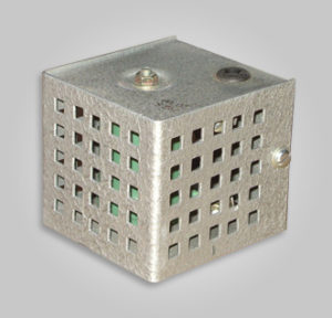
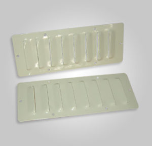 Ventilating dev ices evenly distributes clean and fresh air throughout . This helps to maintain air quality and remove moisture from everyday living activities. Ventilation systems help in providing clean and fresh indoor air. There are various benefits related to ventilating devices. These devices clear out dampness and coldness which lead to illness from houses. Such systems wipe out many things which negatively affects our health. A good ventilating system helps in reducing mould and mildew build ups around the living space. The two major ventilating devices are positive pressure ventilation systems and balanced pressure heat recovery ventilation devices.
Voltmeter Selector Switch
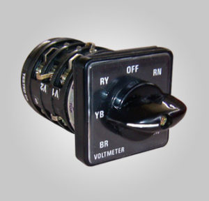 Voltmeter Selector Switch is connected to the Voltmeter, to measure the Voltages between different phases (also, between each phase and neutral, if needed) with a single voltmeter.
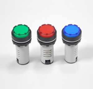
Warning Light
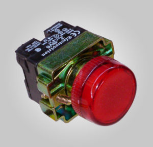
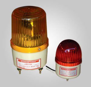 Al Inshrah supplies high quality warning lights at competitive prices. It is a cautionary sign of danger that are visually communicated. Warning lights are normally lights which denotes caution. Al Inshrah sells different types of warning lights for different industries and for different purposes. Warning lights or flashing lights displayed can be blue, green, red, magenta, yellow etc. each conveys different messages and specific warnings.
Relay
 A relay is an electromagnetic switch. In other words it is activated when a current is applied to it. Normally a relay is used in a circuit as a type of switch (as you will see below). There are different types of relays and they operate at different voltages. When you build your circuit you need to consider the voltage that will trigger it.
The main part of a relay is the coil at the center. A small current flowing through the coil in the relay creates a magnetic field that pulls one switch contact against or away from another. Putting it simply, when current is applied to the contacts at one side of the relay the coil allows the contacts at the other side to work. Usually relays are used to turn on a second circuit. The first circuit activates the relay which then ‘turns on’ the second circuit.
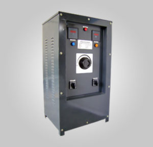
Dimmerstat / Variac / Auto Transformer
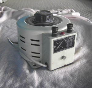
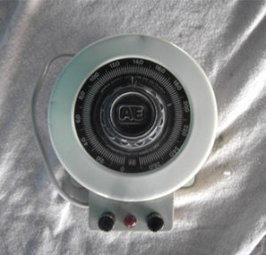 Dimmerstat is an auto transformer which is generally connected to supply which provide us step up /step down output depending on the terminal to which input is connected. Normally there are two ways to operate a Dimmer stat:-
1. The output voltage can be varied from 0 to full supply voltage.
2. Voltage from 0 to 12 % higher than supply voltage
An Autotransformer/auto step down transformer is an electrical transformer with only one winding, In an autotransformer, portions of the same winding act as both the primary and secondary sides of the transformer.The winding has at least three taps where electrical connections are made. Autotransformers have the advantages of often being smaller, lighter, and cheaper than typical dual-winding transformers, but the disadvantage of not providing electrical isolation. Other advantages of autotransformers include lower leakage reactance, lower losses, lower excitation current, and increased KVA rating
Variable autotransformers
 As with two-winding transformers, autotransformers may be equipped with many taps and automatic switchgear to allow them to act as automatic voltage regulators, to maintain a steady voltage at the customers’ service during a wide range of load conditions. They can also be used to simulate low line conditions for testing. Another application is a lighting dimmer that doesn’t produce the EMI typical of most thyristor dimmers.
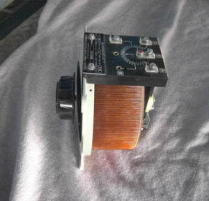 By exposing part of the winding coils and making the secondary connection through a sliding brush, a continuously variable turn’s ratio can be obtained, allowing for very smooth control of voltage. Applicable only for relatively low voltage designs, this device is known as a variable AC transformer (often referred to by the trademark name Variac). The output voltage is not limited to the discrete voltages represented by actual number of turns. The voltage can be smoothly varied between turns as the brush has a relatively high resistance (compared with a metal contact) and the actual output voltage is a function of the relative area of brush in contact with adjacent windings. The relatively high resistance of the brush also prevents it from acting as a short circuited turn when it contacts two adjacent turns. Typically the primary connection connects to only a part of the winding allowing the output voltage to be varied smoothly from zero to above the input voltage and thus allowing the device to be used for testing electrical equipment at the limits of its specified voltage range.
“Variac” and “Dimmerstat” are trade names of variable autotransformers. Hence, they are the same.
Panel Board Accessories
Bakelite Sheets
Bakelite Sheets are made from premium quality raw materials that are highly in demand for their dimensional accuracy, mechanical strength, heat resistance and low absorption of water.We offer these Paper Based Bakelite Sheets, also known as PhelonicLamininated Sheets, is double-sided high-pressure laminate, which is well known for its electrical insulation properties and available in various varieties, grades, and specifications to meet the specific requirements of the clients.
 Type: – Insulation Sheet
Material: Paper Base
Color: Brown, Gray
Application: Low Voltage
Paper Phenolic Sheet as per IS (IS2036-1995) / (BS 2572) – P1, P2, P3 & P4.
European Standard EN 60893-3-4-1995- PF CP201, 203,204 & 206.
Nema Standard LI 1-2001-Nema -X, XP, XX & XXX.
German Standard DIN-7735, HP-2061, 2061.5, 2061.6, 2062.8.
Australian Standard as 1795-1983-type X Meter Panel.
Thickness: 0.5mm to 50 mm.
Bakelite Terminal
Busbar Heat Shrinking Sleeve
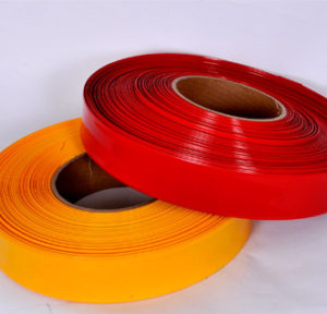
“Shrinking Sleeves” used to Insulate “Bus Bars and Conductors” provide excellent insulation with a High Dielectric Strength & a Good Retention of Dielectric Strength even under Wet Conditions. The sleeves are manufactured from high quality non tracking cross-linked polyolefin material. Meets ANSI C37.20.2 standards for MV switchgear application up to 36 KV.
 Physical & Electrical Properties
Tensile Strength: > 300 kg/Sq. Cm.
Ultimate Elongation : > 250 %
Insulation Resistance : 3 x 10⁶ Mega ohms (at R/T)
Dielectric Strength : 12 KV ( B.D.V. : 15 KV )
Shrink Temperature : 120o Centigrade
Shrink Ratio : MD – 10 % TD – 40 %
Continuous Operating Tempt : – 05 to 110o Centigrade
Corrosive effect – Non Corrosive : Resistant to acid, alkalis & oil
Fire Retardation : Self-extinguishing, Non flammable
Type : Creased type
Sizes Available : L/F size 41mm to 240 MM
Bus Bars Size : 25 x 6 to 200 x 12 MM
Thickness : 0.20 to 0.40 MM
Std. Color : Red, Yellow, Blue & Black
Std. Length / Roll : 50 to 100 meters
Shelf Life : 6 months, stored below 25o Centigrade
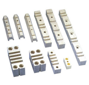
Busbar Support
The busbar supports are used to create a 3 or 4-pole busbar system with conductor heights from 30 – 100 mm. The bar can have both individual conductors and double conductors per phase. Different phase center spacings permit adaptation of the busbar system to different room dimensions or concepts with different short-circuit strengths. The nominal operating voltage according to IEC 61439 is 1000VAC or 1500VDC.
When it comes to short-circuit current, a distinction is made between surge current and continuous short-circuit current. It is the continuous short-circuit current that is responsible for heating the conductor. It is proportional to the current square I² and the duration of the short circuit t.
The surge current generates the maximum force that is exercised on the current-carrying conductors and therefore on the supports. The spacing between two neighboring supports can be changed to absorb the forces of the maximum expected surge current. This dependence for supports SH1 and SH3 is shown in the diagram. With a given current, this permits calculation of the maximum admissible spacing between the busbar supports for different bar formats. The maximum spacing differs between busbar supports.
 Surge current
With a Cu bar measuring 30×10 mm and a support spacing of 250 mm, the maximum short-circuit current is 110 kA
The busbar supports are made of glass fiber-reinforced polyamide 6.6 and are self-extinguishing in line with UL 94 V0. The material permits a maximum bar temperature of 120°C and is halogen free. The top and bottom sections of a support are identical, thereby ruling out the problem of interchanging. The two support sections are connected to each other via threaded rods or threaded bolts. The spacing of the support sections is defined by so-called spacers to suit the bar height.
5 supports are required for laying within a switch cabinet. This is why the busbar supports are available in packs of 10, equivalent to 5 supports.
The length of the required threaded rods depends on the bar height plus the length for securing of the support on the base structure.
Din Rail Terminals
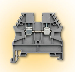 A full range of single-level and two-level feed-through screw connection DIN-Rail terminal, test, disconnect and grounding blocks.
Many blocks are available in multiple colors for easy circuit identification, plus popular single and double-bridge shaft systems for maximum power distribution flexibility. Certifications include UL1059, cURus, IEC60998 and IEC60947-7.
High Short-Circuit Current Rating (SCCR) rated to help ensure compliance with NEC® 110.10
Available side-insertion and top-insertion bridges offer unmatched power distribution possibilities
Multiple colors, partition plates, marking system and labels provide easy circuit identification
UL 94V0 Flammability rated material with superior electromechanical properties
Zinc-plated steel wire cage and tin-plated copper conductive elements assure high pressure contact force and low voltage drop.
ELCB
An ELCB is a specialized type of latching relay that has a building’s incoming mains power connected through its switching contacts so that the ELCB disconnects the power in an earth leakage (unsafe) condition. The ELCB detects fault currents passing from live (hot) to the earth (ground) wire within the installation it protects. If sufficient voltage appears across the ELCB’s sense coil, it will switch off the power, and remain off until manually reset. An ELCB however, does not sense fault currents passing from live to any other earthed body.
An Earth Leakage Circuit Breaker (ELCB) is a safety device used in electrical installations with high impedance to prevent shock. It detects small stray voltages on the metal enclosures of electrical equipment, and interrupts the circuit if a dangerous voltage is detected.
RCCB:-A residual current device (RCD), or residual current circuit breaker (RCCB), is an electrical wiring device that disconnects a circuit whenever it detects that the electric current is not balanced between the phase (“hot”) conductor and the neutral conductor. Such an imbalance is sometimes caused by current leakage through the body of a person who is grounded and accidentally touching the energized part of the circuit. A lethal shock can result from these conditions; RCDs are designed to disconnect quickly enough to mitigate the harm caused by such shocks.
 Difference between ELCB & RCCB
ELCB is a device that is used to detect leaking currents from an installation when the power is cut while RCCB is an electric device that disconnects power when the flow of power is not balanced at phase.ELCB has a protection for earth leakage whereas the RCCB has the dual protection features of ELCB and MCB
ELCB is a voltage operated device.RCCB is a current operated device.IN ELCB, Trip coil is connected between system ground and non-current carrying part of the machines.RCCB having CBCT(Core Balanced Current Transformer).CBCT consists of 2nos of primary winding (P1,P2) and one secondary winding(S1).Primary windings are in series with the load and secondary winding connected to Trip coil. In case of healthy time, voltage in both the primary windings will be cancelled and hence no voltage on secondary winding. During the leakage or If anybody touch the live wires of the machines, current will passing through the body and connected to ground. It will cause the voltage difference in primary windings and induced voltage in secondary operates the trip coil (operating time 50ms).
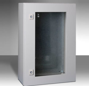
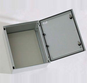
Enclosure
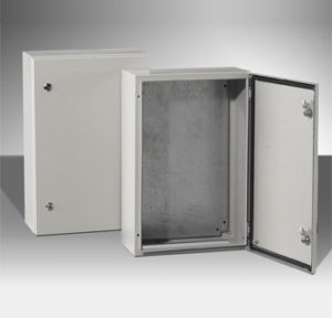
We cover a huge range of electrical enclosures, Our Enclosures adhere to the IEC’s standards for determining enclosures’ capabilities. Their International (or Ingress) Protection IP rating system defines an enclosure’s protective capacity, and then assigns an IP Code. The code labels an enclosure’s IP followed by two numbers; the first digit shows the extent to which equipment is protected against particles, and the second digit indicates the extent of protection against water. Our IP54 enclosures have a high level of protection against particles, and a fair amount of protection against water. All of our enclosures rigorously comply with the guidelines, so you can count on quality and cost-efficient enclosures.Our most common IP ratings are probably 65, 66, 67 and 68. So for quick reference, these are defined below:
 IP65 Enclosure – IP rated as “dust tight” and protected against water projected from a nozzle.
IP66 Enclosure – IP rated as “dust tight” and protected against heavy seas or powerful jets of water.
IP 67 Enclosures – IP rated as “dust tight” and protected against immersion.
IP 68 Enclosures – IP rated as “dust tight” and protected against complete, continuous submersion in water.
Features of our cabinets include:
1. Customizable metal finishes, including aluminum alloys, stainless steel, galvanized steel and carbon steel, to meet your application requirements. Finishes available include wet coat and powder coat painting, anodizing
2. Security and tamper-resistant hardware
3. Environmental controls, including thermostats, heat strips, air conditioning, passive or fan-assisted venting and insulation
4. Light switches
5. Viewing windows
6. Fuse blocks and power panels
7. Casters, support legs and risers
8. Range of installation options, including free-standing, pad mounted, wall mounted, pole mounted and walk-in
 Electrical enclosures are rated by Type (NEMA 250 / UL 50, 50E), and/or IP rating (IEC 60529) based upon the degree of protection provided. Type ratings and IP ratings have only the following in common:
1. A degree of protection for persons from hazardous components inside the enclosure
2. A degree of protection for equipment inside the enclosure from ingress of solid foreign objects, including dust
3. A degree of protection for equipment inside the enclosure from ingress of water
NEMA 250 and UL 50, 50E Type rating documentation defines additional requirements that a Type-rated enclosure must meet. These include:
Mechanical impact on enclosure walls
Gasket aging and oil resistance
Corrosion resistance
Door and cover latching requirements
Sheet metal gauge construction requirements (UL 50 only)
Electrical enclosures that carry only an IP rating have not been designed or tested to the additional Type-rating requirements. For this reason, and because the tests and evaluations for other characteristics are not identical, the IP ratings cannot be exactly equated with NEMA enclosure Types.
 IP Ratings
IP (or “Ingress Protection”) ratings are defined in international standard EN 60529 (British BS EN 60529:1992, European IEC 60509:1989). They are used to define levels of sealing effectiveness of electrical enclosures against intrusion from foreign bodies (tools, dirt etc) and moisture.
Numbers in an IP Rating
The numbers that follow IP each have a specific meaning. The first indicates the degree of protection (of people) from moving parts, as well as the protection of enclosed equipment from foreign bodies. The second defines the protection level that the enclosure enjoys from various forms of moisture (drips, sprays, submersion etc).
Insulator HV & LV
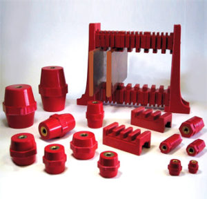 Bus Bar Insulators mainly made from bulk molding compound, unsaturated polymer with fiber glass. Product itself are with good properties such as electrical resistance, hear resistance, fire resistance, low shrinkage, water resistance.
Characteristics
1. Polyester without halogen.
2. UL94 VO self-extinguishable.
3. Colour red RAL 3002.
4. Operating temperature from – 40oC to + 130oC.
5. Deformation under load temperature (ASTM D643): 200oC
6. Dielectric constant (ASTM D150): 4/5.
7. Arc resistance (ASTM D495): > 180 s.
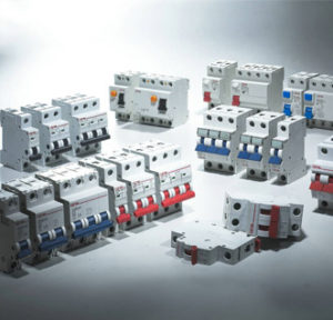
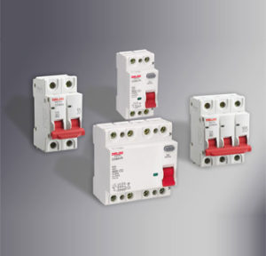
MCB (Miniature Circuit Breaker)
 A circuit breaker is an automatically operated electrical switch designed to protect an electrical circuit from damage caused by overload or short circuit. Its basic function is to detect a fault condition and interrupt current flow. Unlike a fuse, which operates once and then must be replaced, a circuit breaker can be reset (either manually or automatically) to resume normal operation. Circuit breakers are made in varying sizes, from small devices that protect an individual household appliance up to large switchgear designed to protect high voltage circuits feeding an entire city.
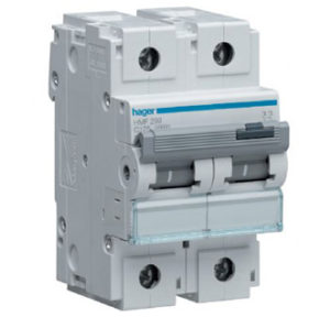
A Miniature Circuit Breaker (MCB) is a device that switches and/or protects the lowest common distributed voltage in an electrical system. It is designed to protect conductors and insulation from damage due to overload and short circuit.Miniature circuit breakers are not just for residential applications only. They are used in residential, commercial and industrial applications.In an industrial or commercial application, miniature circuit breakers can be found in load centers, lighting panel boards and individual mountings.
Miniature circuit breaker construction is simple, yet very precise. In fact, a miniature circuit breaker has no replacement parts. It is not designed to be maintained. When a unit goes bad, it is simply replaced.
 The trip unit is the brain of the miniature circuit breaker. It activates the operating mechanism in the event of a prolonged overload or short circuit. This type of circuit breaker uses a thermal magnetic mechanism. This is the predominant trip unit technology used in the domestic market. A bimetal and an electromagnet work together to provide overload and short-circuit protection.
Specifications for miniature circuit breakers vary widely. As such, there is a miniature circuit breaker to fit virtually any application, standard, and local code requirement. In general, miniature circuit breakers are often categorized by the following:
Ratings
Number of poles
Mounting methods
Miniature circuit breakers are typically available in single pole and double pole types. A pole is a hot conductor. It is a space in a load center, panel board, or similar device where a breaker can be attached. A single pole breaker disconnects one conductor, and a double pole breaker disconnects two conductors. Single pole breakers are associated with 120 volts, while double pole breakers are associated with 240 volts.
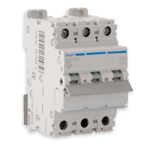
Three pole miniature circuit breakers are available, but are not as popular as the other two types. They are typically used in industrial applications. Miniature circuit breaker poles are generally one inch in width. However, some breaker designs allow two poles to fit in the standard one-inch space. This breaker type is called a duplex circuit breaker (or “half-size branch circuit breaker”).
Miniature circuit breakers fall into two categories. These are:
Residential
Residential miniature breakers are only of the plug-in type. These are designed for residential load centers, commercial units, and light industrial applications. They typically range from 10 to 125 amps, with an interrupting rating of 10 or 22 KAIC.
Industrial
These breakers are designed for three types of mounting applications: plug-in, bolt-on, and cable-in/cable-out. (We will look at mounting methods shortly.) Industrial miniature breakers are designed to protect small branch circuits in commercial or industrial electrical distribution systems. They are applied in load centers, lighting panel boards or individual mounting applications. They typically range from 6 to 125 amps, with an interrupting ratings as high as 65 KAIC.
MCCB (Molded Case Circuit Breaker)
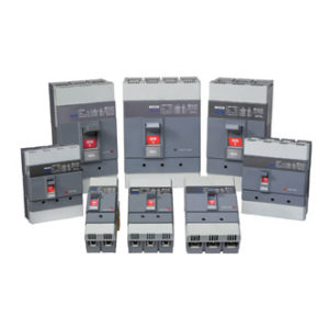 A circuit breaker is an automatically operated electrical switch designed to protect an electrical circuit from damage caused by overload or short circuit. Its basic function is to detect a fault condition and interrupt current flow. Unlike a fuse, which operates once and then must be replaced, a circuit breaker can be reset (either manually or automatically) to resume normal operation. Circuit breakers are made in varying sizes, from small devices that protect an individual household appliance up to large switchgear designed to protect high voltage circuits feeding an entire city
The traditional molded-case circuit breaker uses electromechanical (thermal magnetic) trip units that may be fixed or interchangeable. An MCCB provides protection by combining a temperature sensitive device with a current sensitive electromagnetic device. Both these devices act mechanically on the trip mechanism.
Depending upon the application and required protection, an MCCB will use one or a combination of different trip elements that protect against the following conditions:
1. Thermal overloads
In an overload condition, there’s a temperature buildup between the insulation and conductor. If left unchecked, the insulation’s life will drastically reduce, ultimately resulting in a short circuit. This heat is a function of the square of the rms current (F), the resistance in the conductor (R), and the amount of time the current flows (t).
If you monitor current flow and time, you can somewhat predict and detect overload conditions. By using a time-current curve, as shown in Fig. 1, you can see the boundary between the normal and overload conditions. Here, we see that the thermal or overload element of the MCCB will initiate a trip in 1800 sec at 135% of rating (shown here as Point 1), or in 10 sec at 500% of rating (shown here as Point 2).
2. Short circuits
Usually, a short circuit occurs when abnormally high currents flow as a result of the failure of an insulation system. This high current flow, termed short-circuit current, is limited only by the capabilities of the distribution system. To stop this current flow quickly so that major damage can be prevented, the short circuit or instantaneous element of an MCCB is used.
A typical time current curve for an instantaneous element, as shown in Fig. 2, shows that it will not initiate a trip until the fault current reaches or exceeds Point 1.
3. Ground faults
A ground fault actually is a type of short circuit, only it’s phase-to-ground, which probably is the most common type of fault on low-voltage systems (600V or less).
Usually, arcing ground-fault currents are not large enough to be detected by the standard MCCB protective device. But, if left undetected, they can increase sufficiently to trip the standard protective device. When this happens, it usually is too late, and the damage is already done. An example of this is a motor having an internal insulation failure. While the current flow may be small, it must be detected and eliminated before major motor damage takes place.
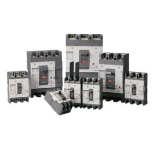 MCCB (Molded Case Circuit Breaker)- is thermal operated for over load current and magnetic operation for instant trip in short circuit condition.under voltage and under frequency may be inbuilt. Normally it is used where normal current is more than 100A. Its rated current is up to 2500 A. Thermal or thermal-magnetic operation. Trip current may be adjustable in larger ratings. MCCB is having some special characteristics over MCB. It protects loads from over current, short circuit current and earth fault protection.
MCCB IS USED FOR HIGHER CURRRENT RATING.ONE MORE DIFF IS THAT MCCB HAS HIGHER SHORT CIRCUIT BREAKING CAPACITY THAN MCB.
MCCB Was originally an IEC term meaning Molded Case Circuit Breaker, but has been very well adopted in NEMA world now, at least at the engineering level. Many rank and file electricians still are not familiar with that acronym because its widespread use in NEMA world is fairly recent. MCCBs generally range from 15A to 1600A, with a few exceptions at either end, and generally start at 14kAIC but go up to 100kAIC for applications with high fault current capacity. There are versions that are Current Limiting (CL) as well. MCCBs are typically sealed units and cannot be serviced, although in larger sizes there are versions with interchangeable parts that can be replaced such as trip units and switch bodies.
Panel Mount Indicators
Rail
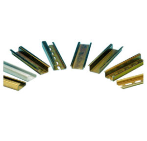 A DIN rail is a standardized thirty five millimeter wide metal bar that has a hat-shaped cross section which is widely used for mounting circuit breakers,relays , meters etc and industrial control equipment inside equipment racks. The abbreviation “DIN” stands for DeutschesInstitutfürNormung, the German organization of standards that defines the size and shape of DIN rails. A DIN rail’s length can be cut as needed by the person installing the rail and circuit breakers
The standard DIN rail used is 35mm wide. However, there are types of the rail having lesser widths such as 15mm or 7.5 mm.
The European Standard EN 50022 and the IEC standard 60715 specify the DIN rail for mounting low voltage switchgear and control gear.
There are three major types of DIN rail:
1. Top hat section, type O, or type Ω, with hat-shaped cross section.
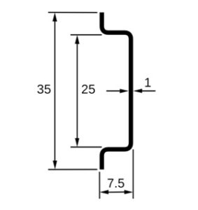 This 35-mm wide rail is widely used to mount circuit breakers. The EN 50022 standard specifies both a 7.5 mm (shown above) and a 15 mm high version, which are officially designated
top hat rail EN 50022 – 35 × 7.5
top hat rail EN 50022 – 35 × 15
Some manufacturer’s catalogues also use the terms Top hat section / Type O / Type Omega (Ω)
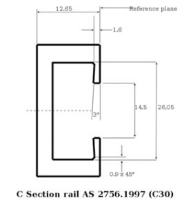
2. C section
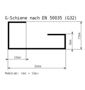
3. G section
G-type rail (according to EN 50035, BS 5825, DIN 46277-1).
RCD-RCCB
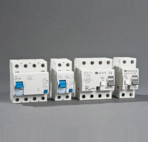 A residual-current device (RCD), or residual-current circuit breaker (RCCB) or residual twin-direct current couplet (R2D2), is an electrical wiring device that disconnects a circuit whenever it detects that the electric current is not balanced between the energized conductor and the return neutral conductor. Such an imbalance may indicate current leakage through the body of a person who is grounded and accidentally touching the energized part of the circuit. A lethal shock can result from these conditions. RCCBs are designed to disconnect quickly enough to prevent injury caused by such shocks. They are not intended to provide protection against overcurrent (overload) or all short-circuit conditions.
The Fault current overloads and short circuits can be detected by circuit breakers like MCB’s MCCB’s& HRC Fuses etc. But, Circuit breakers don’t detect leakage currents, which are dangerous for humans and livestock and if not detected can lead to fire hazards. We need a solution that detects such leakages currents and disconnects the circuits from the power supply. The solution is RCCB (Residual Current Circuit Breaker) also known as ELCB (Earth Leakage Circuit Breaker) which provides protection against direct and indirect contact of personnel or livestock and against probable fires.
 RCCB works on the principle that in an electrical circuit the incoming current is the same as outgoing current as shown in the Diagram. RCCB incorporates a core balance transformer having primary and secondary windings and a sensitive relay for instantaneous detection of fault signal.
The primary winding lies in series with the supply mains and load. Secondary winding is connected to a very sensitive relay. In a faultless situation, the magnetizing effects of the current carrying conductors cancel each other out. There is no residual magnetic field that could induce a voltage in the secondary. During flow of leakage current in the circuit an imbalance is created in the circuit which gives Rise to leakage flux in the core. This leakage flux generates an electrical signal that is sensed by the relay and it trips the Mechanism thereby disconnecting the supply. When pressing the TEST button ‘T’, a fault is simulated via the Test resistance & RCCB trips.
Terminals
 A terminal is the end of a wire that can be fitted with a connector to provide a connection from one electronic device to another.
An electrical connector is an electro-mechanical device for joining electrical circuits as an interface using a mechanical assembly. Connectors consist of plugs (male-ended) and jacks (female-ended). The connection may be temporary, as for portable equipment, require a tool for assembly and removal, or serve as a permanent electrical joint between two wires or devices.[1] An adapter can be used to effectively bring together dissimilar connectors.
There are hundreds of types of electrical connectors. Connectors may join two lengths of flexible copper wire or cable, or connect a wire or cable or optical interface to an electrical terminal.
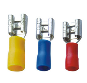
We carry a large selection of quality wire terminals. include ring terminals, push-on terminals, bullet terminals, spade or fork terminals, and butt splices. are manufactured from tin-plated copper for maximum conductivity, and come in either bare non-insulated form, with vinyl insulation, more durable nylon insulation, or high performance heat shrink insulation. High temperature wire terminals made from nickel plated steel are also available that can handle temperatures up to 900°F. Most terminals are available for wire sizes from 22 gauge to 10 gauge. We also carry butt splices, ring terminals, and copper eyelets for wire sizes from 8 gauge to 4/0.
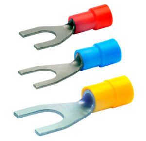 ring terminals and spade terminals (sometimes called fork or split ring terminals). Electrical contact is made by the flat surface of the ring or spade, while mechanically they are attached by passing a screw or bolt through them. The spade terminal form factor facilitates connections since the screw or bolt can be left partially screwed in as the spade terminal is removed or attached. Their sizes can be determined by the size of the conducting wire AWG and the screw/bolt diameter size designation.
Testing Equipments
Power Frequency High Voltage Tester
C.T. Polarity Tester
Digital ME Tester
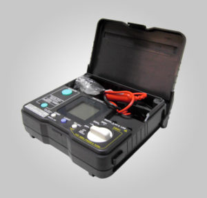
ELCB Tester
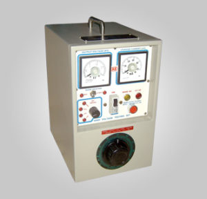
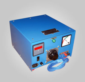
Milli Volt Drop Test Set
 Input Voltage : 200/230-V, 50 Hz, AC supply.
Input Current : 3.5 Amps
Output Current : 0-200 Amps Continuous
Output Voltage : 0-6 Volts OCV
Cooling : Air Cooled
Rating : Continuous For Testing
Ripple : Within 5%
Accuracy : ± 1%
Metering: 96 Sq. mm Moving Coil type Ampere Meter & 96 Sq. mm Digital mV meter.
Leads: (i) Lead with Crocodyle – 1.5 mtrs.
(ii) Current Leads – 3 mtrs.
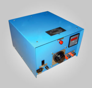
Primary Current Injection Test Set
 Input : 240 Volts, 1 Phase, 50 Hz. A.C.
Output : 0 to 2 Volts / 3000 Amps. 0 to 240 Volts / 28 Amps.
Duty Cycle : Continuous Minute ON, Minute off
Cooling : Natural Air Cooled (AN). Natural Air/Oil Cooled Section.
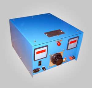
Secondary Current Injection Test Set
 Input voltage: 240 V 50 Hz, Single phase, AC supply.
Output voltage variable: 0-200 V AC at 1 Amp.
0-200 V DC at 1 Amp.
Output Current: 0-5 A Continuous and upto 10 A for short duration.
Cooling : Air cooled
Duty : Testing continuous.
Amperemeter with built in CT : Digital 3½ digit
Digital Timer: D0.0001 – 9999 Sec.
Voltmeter: Digital 3½ digit 0-300 V AC/DC
Tools
Tools
- Hydraulic Machine Set With Table
- Hydraulic Bending Machine
- Hydraulic Punching Machine
- Hydraulic Cutting Machine
- Hydraulic Hand Pump
- Hydraulic Foot Pump
- Hydraulic Hand Cutting Machine
- Crimping Tools
- Wiring Tools
- Hand Crimping Tools
- Cable Cutter
Other Products
Testing Equipments
- 24 Hours Analoge Timer
- 24 Hours Digital Timer
- Adaptor & Gland Bush
- Battery Charger & Power Supply
- Bulb Filament Type
- Bulbs
- Buzzer
- Cable
- Cable Gland
- Cable Lug
- Cable Marker
- Cable Tie
- Capacitor
- Change – over switch
- Clamp Meter
- Contactor
- Control Transformer
- Copper Bush
- Copper Lug
- Current transformer(CT)
- Din Rail mounting insulators
- Direct online starter (DOL)
- Earth Bar
- Earth link
- Finolex PVC Sheet
- Flexible Pipe
- Foot switch
- Fuse
- Fuse base
- Fuse carrier
- Fuse puller
- GI Cable Trunking & Fitting
- Hardware
- Heat Shrinking Sleeves
- Hole plug
- Indicators
- Insulation Tape
- Insulators
- Load Break Switch
- Load breaker Switch
- Load Breaker Switch
- Louvre
- Meter windows (viewing window)
- Meters
- Movable bush
- Neon bulbs
- Neutral link
- Panel Trunking
- Photo Cell
- Potentiometer
- Power Factor Regulator
- Reactive Power Regulator
- Rectifier
- Shunt
- Sliding nut
- Solenoid Valve
- Spiral Band
- Star Delta Starter
- Star-delta starter
- Step down Transformer (power transformer)
- Step Down/Power Transformer
- Step Switch
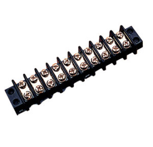
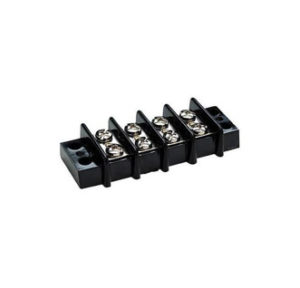
- Terminal Block
- Tie Mount
- Treadle Switch